Design and Implementation of Real-time System Data Channel in Thermal Power Plant
Walk behind Laser Screed is mainly used in large area concrete construction, such as large workshop, airport, the plaza and so on.
- Adopts imported laser transmitter and receiver.
- Hydraulic drive, strong power.
- Electric control screed head.
- Adopts Honda gasoline engine with electric start.
- Two kinds of tyres optional.
- Integrated computer controller, easy to operate.
Walk-Behind Laser Screed,Manual Walk-Behind Laser Screed,Somero Laser Screed,Somero S485 Laser Screed Jining Furuide Machinery Manufacturing Co., Ltd. , http://www.furdroller.com
0 Introduction Modern power generation companies are mostly equipped with powerful automation control systems and management information systems (MIS), and the links between them are increasingly close. For example, in power generation enterprises, MIS includes both the management of business information and the management of production information. The latter, which production management personnel require at all times, must be real-time. For this reason, MIS is often connected with the automation control system, and the real-time information required by the manager is processed in real time in the production automation system to reflect the real-time status of the production, and sent to the MIS for professional management personnel [1]. Such a system is called real-time data management information system (RT-MIS), or short-term real-time information system. It is indispensable for power companies' production, operation and management units, and plays an increasingly important role in the management of enterprises.
The core of the real-time information system is the data channel. The design and development of the system is also centered on the data channel. In the transformation project of a real-time production of a thermal power plant, we first carried out preliminary planning of the following two core issues in the system data channel: 1 In the data communication of MIS and DCS, SCADA and other automated control systems, some are now used Socket network communication, some use FTP communication. Obviously, the intermediate medium of the former method is a memory space, which has a high transmission speed and high efficiency, but requires the preparation of a Socket sending and receiving program; the intermediate medium of the latter method is a file, and the transmission speed is slow and inefficient, but it can be used directly. FTP service to complete the network transmission. According to the reality of the plant, the former method is used to improve the performance of network data communication. 2 In the MIS network information publishing and receiving architecture, the traditional customer/server 2-tier structure (ie C/S structure) and Web browser/Web server, database (DB) server 3-tier structure (ie, B) are often used. /S structure). The latter of the two structures is derived from the former, and their essence is C/S. The core of database services is also consistent, but due to the difference in structure, the two suitable user objects are different [2]. However, there are many problems in the two-tier structure C/S model, such as high development and maintenance costs, heavy client load, poor flexibility, lack of openness, difficulty in linking with the Internet/Intranet, and many problems in system use and maintenance. In view of this, and taking into account the complete integration of the new production real-time system with the Web-based MIS of the plant, the B/S structure is used in the design of the real-time system, which also complies with the current development trend of Internet/Intranet technology applications. .
1 Requirements Analysis The main purpose of the real-time information system is to manage the real-time data of production operations. Help related professional management departments to improve the management level of production operations so as to achieve the purpose of safety, stability, and economic operation [1]. Its main functions are: real-time screen display, operation data storage and processing.
The system data channel provides support for the collection, transmission, processing, storage, and interaction with the user of all the above related data.
The real-time monitoring target of the power plant mainly includes unit units (including sub-systems of the unit) and the electric remote control system of the whole plant. For example, the data collection capacity of a unit in a power plant is approximately: 500 to 600 points analog, 400 to 500 points; the main data collected are: temperature, pressure, speed, vibration, displacement, flow, voltage, Current, generator stator/rotor load, furnace side temperature, pressure, flow rate, oxygen, etc. The data is mainly derived from DCS. The plant's electric telecontrol system mainly collects the voltage, current, active and reactive power output, transmission power, and the opening/closing position of each switch knife on the main transformers, switches, busbars, etc., and the analog quantity is about 200. More than 100, the data mainly comes from remotely operated SCADA.
2 Overall Design The real-time system of a power plant The physical structure of a remote unit and its related system of a unit and the entire plant is shown in Figure 1. The actual physical path in the figure corresponds to the actual system. 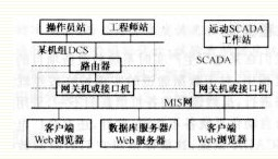
- Actual physical path; ... Optional physical path; - Logic isolation
Fig. 1 The real-time system of the physical structure of a certain unit and the remote part of the whole plant in a real-time system of a power plant Real-time system Real-time data is obtained from the power plant DCS, DEH, SCADA, and other production and operation automation systems, and processed into real-time information required by managers. MIS. For a unit part, because the power plant DCS network segment and the MIS network segment are isolated from each other, then set up a router between the two networks and set up a gateway machine or set up an interface machine on the MIS network to complete the data transfer task (the gateway machine can Directly or through a router connected to the DCS network). The gateway machine configures two network cards to communicate with the DCS network and the MIS network respectively. For the remote SCADA part, because the SCADA system and the MIS network are also isolated from each other, a gateway machine is also set up between the two to perform real-time data collection, processing, and transmission. The gateway machine communicates with the SCADA workstation through the serial port (COM port) on the one hand, and communicates with the MIS through the network card on the other hand.
Thereafter, the database server on the MIS network receives real-time data from the gateway machine or interface machine, and processes and stores it; the Web server is usually co-located on the same physical server with the database server, ie, the real-time system server, and the database server and the client. The browsing system cooperates to provide MIS users with real-time data and pages.
According to the above physical structure, the real-time system of the power plant adopts Socket network communication or serial port communication based on TCP/IP protocol in the data communication between the gateway machine (or interface machine) and the production and operation automation system such as DCS and SCADA (now the DCS station of the power plant All network services support Socket network programming interface based on TCP/IP protocol, so this method has more universal applicability. In the aspect of network data communication between MIS and gateway machine (or interface machine), the TCP/IP protocol is adopted. Socket network programming interface and UDP mode communication; in the MIS network information release and receive architecture, the use of three-tier structure of B / S mode.
The overall block diagram of the plant-wide real-time system data channel with the core of data collection, processing, transmission, storage, and data flow during user interaction is shown in Figure 2. 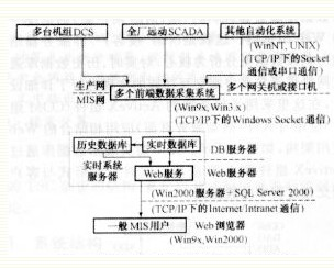
Figure 2 Overall block diagram of a real-time system data channel for a power plant
The arrows in the figure indicate the front-end data acquisition system of the production and operation automation system from DCS, SCADA, etc. to the gateway machine (or interface machine), the front-end data acquisition system to the database service system on the MIS network real-time system server, and the database server on the MIS network/ Web server/Web browser data flow in a three-tier structure. The brackets in the figure indicate the communication methods between the operating platforms and systems on each system.
3 implementation program can be seen from Figure 2, front-end data acquisition system is the function from the DCS, SCADA production and operation automation system to obtain real-time data sent to the database server. For a unit DCS of the power plant, its workstation is built on top of the WinNT operating system. The TCP/IP-based Socket network programming interface and UDP communication mode are supported on the network service. Under this scheme, the DCS workstation sends real-time data packets, the front-end data acquisition system receives the data packets, and after processing, the data packets are sent to the database server of the MIS network, and are received and processed by the data dump system on the database server. Stored in real-time database and historical database. The data communication between the DCS and the front-end data acquisition system and the data communication between the front-end data acquisition system and the MIS network real-time system server are in the form of datagrams, and the data storage (ie, the database) is in the form of "unified index table + grouped data table". For the remote control SCADA at the plant, the workstations and the front-end data acquisition system communicate with each other via the serial port. The communication supports the interrupt mechanism and data queue. The other parts adopt the same data transmission and storage formats as above.
For the three-tier B/S structure in Figure 2, Web services and database services are often combined on a single hardware server (that is, a real-time system server in the figure). At this time, for the network, they can also be viewed logically as a server and called an interactive network database server, while the client (MIS user side) is a unified Web browser. This is the so-called "thin client / fat server structure." Still taking the data flow analysis as the core, the real-time and historical database is designed in detail through the realization of the interaction function between the network channel and the client. Here, a relatively new ActiveX component (COM component) application and ASP (Active Service Page) application are adopted. The combined web application architecture is shown in Figure 3. The arrows in the figure indicate the flow of data in the process of the database interacting with the client in the form of real-time pages through ActiveX components and ASP applications. 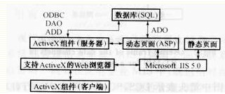
Figure 3 Web application structure diagram of ActiveX components, COM components and ASP applications
In the above structure, on the one hand, modules accessed to the database are embedded in web pages in the form of ActlveX controls for use by web browsers (such as IE). Only static HTML pages are saved in the web server, and users access web pages using a web browser. , Read static images and related information from the Web server, real-time data from the downloaded to the local ActiveX controls responsible for reading and displaying; On the other hand, use ASP technology to handle part of the database access and dynamic page display tasks.
ASP is a server-side scripting environment. When a browser requests an ASP file from a Web server, the script code starts to execute. Because the script code runs on the server and not on the client, the script code is not directly sent to the server. In the browser, only the results of the script run are sent to the web browser. This type of web application implemented in ASP is also called an ASP application. However, it is difficult to fully implement the interaction between the MIS user and the database by using the ASP application. Therefore, the method of combining the ActiveX component with the static HTML page and the dynamic page ASP implementation method are used together to achieve the respective advantages.
ActiveX controls are embedded in Web pages through markup statements.