Various drive concepts in machine tool use
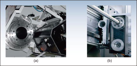
We usually cannot learn the details of the various drive technologies used by the machine tool just by looking at it. In principle, if you want to complete the action that needs to be performed, it is possible to select the main drive, feed drive, or auxiliary drive. Main drive: The main drive is mainly closed-loop control, and most of them use synchronous or asynchronous motors. Practical applications include vehicle motors, milling machines and grinders, and kit motors or housed motors used in machining centers. A conventional spindle drive with a main motor is a widely used main drive, most of which uses air cooling. If you consider indirect or pie-derived costs, the cost of this method is lower than that of the motor spindle system. On the other hand, adding a gearbox to the spindle can translate angular velocity and torque into the machining task, but in turn, the gearbox can generate excess radial forces, introduce noise, and increase wear. At the same time, the use of master motors with integrated motors (with integrated spindles) is technically mature. Thanks to the possibility of not using gearboxes and clutches, these drives are capable of rotating around the center without shearing; and because they can run smoothly for a long period of time and are subjected to minimal wear, these drives stand out, especially at high speeds. Performance during machining. At present, the cost required to generate higher torque is still high, because it means that planetary gears must be integrated in the crankshaft or more powerful motors must be selected. In order to achieve regular maintenance and repairs, it is a standard to integrate monitoring sensors into the spindle in order to obtain measurement data. The use of oil, air or ethylene glycol for cooling is still essential. Feed drive: The choice of feed drive technology is mainly concentrated between electromechanical or hydraulic systems. In order to make the right choice, it is necessary to carefully consider the advantages and disadvantages of the two systems. In an electromechanical feed actuator, a servomotor that assembles a ball screw is currently in a dominant position. It can convert rotational motion into linear motion. Here, synchronous main motors are preferred because they can meet the higher requirements for positioning, synchronous operation, and dynamics of the feed driver compared to the main drive. Due to the high static stiffness of the feed drive system, it is suitable for a wide range of applications and has always been considered a traditional choice. However, it has a disadvantage that it is easy to wear. Depending on the installation conditions and the required torque strength, the servomotor can be connected to the spindle either directly or indirectly (eg via a synchronous belt). Although the principle of linear motors was available as early as the 19th century, it was not until the early 1990s that the technology entered the field of machine tool applications. At the time, Rexroth assembled the first series motor with a linear motor. This type of driver has the advantages of wear resistance, high stiffness, and good dynamic performance, and can be satisfactorily of excellent quality. This means that compared to a ball screw assembly with an indirect position detection system, this type of drive guarantees a high-precision, trouble-free operation of the system over long periods of time. load capacity The load capacity of a driver is one aspect that limits its use. Of course, this does not mean that when faced with greater resistance, ball screw assembly and hydraulic drive solutions cannot be used. Another major criterion for measuring motor drives is to measure their actual ability to support machine components, such as a shwarf cover with a maximum allowable sliding speed and a rack rail with damping behavior. The benefits of linear motor drives have been greatly reduced due to the associated increase in investment costs. As of now, this shortcoming has prevented the drive technology from achieving breakthroughs on a global scale. F1: The hardware part of machining must have a long life In this case, the need for a hydraulic feed driver has greatly increased. Of course, the reasons for this result are also closely related to the limited installation space, the need for high dynamic performance, and the generation of large feed forces. Of course, the installation accuracy of the hydraulic feed driver needs to reach the micron level. Practical applications have repeatedly demonstrated that hydraulic linear actuators have a long service life and are often more durable than actuators equipped with ball screws. There is no need to install feed actuators based on special properties such as torque and rotation speed. The hydraulic shaft can draw energy from the hydraulic fluid accumulator on demand, which means that the input power can be reduced by up to 80%. Auxiliary Drivers: With regard to auxiliary drives, there are now a wide variety of solutions. Among the series of auxiliary drive functions of the machine tool, neither of the programs has developed a clear development trend, nor has any of them passed the test and can stand out. The choice of a solution depends entirely on the needs of the actual driving situation. Thus, for a group of machine tools whose function sequence is determined, it is very common to combine various types of drive technologies. There are no shortages of such phenomena in practical applications. For example, one can use an electromechanical actuator that drives the toolholder vertically or diagonally in combination with a hydraulic or pneumatic gravity compensation device. Here, gravity compensation can be broadly understood as a passive auxiliary drive whose task is to compensate for the mass of a moving object. Gravity compensation can be implemented in many ways, of which the most widely used is a hydraulic solution with a hydraulic flow accumulator. If the value of the gravitational force that needs to be compensated is small, a pneumatic spring can be used to complete the compensation. The advantages of these solutions lie in their flexible dynamic behavior and good energy balance capabilities. Due to its small weight, simple control structure and fast movement speed, the pneumatic drive is very suitable for installation in a handling device. This method is also suitable for smaller feed and load units, so these units can be integrated into the flow of the production process. In machine tools, clamping tools and workpieces is extremely important because the quality of the processing results is largely influenced by the accuracy and repeatability of the clamping process. Hydraulic splints are representative of dedicated auxiliary drives and are particularly popular in machine tools with automatic loading and unloading of workpieces due to their ease of automation. Conclusion: A variety of electrical, hydraulic, electro-mechanical, and pneumatic drive schemes can be used in the machine tool to complete the drive task. Design engineers and their teams need to consider various constraints and decide which driver to use to complete the task. In-depth understanding of the excellent automation suppliers of various technologies should also fully compare the advantages and disadvantages of various technologies and make recommendations to users accordingly. Ceramic Plate,Color Glaze Ceramic,Stoneware Plate Bowl Mug,Kitchen Dinner Ware Set HANDAN OURAY I/E CO., LTD , https://www.ourayceramicware.com