Research on Application of PID Control Algorithm Based on FF Fieldbus
Decoration,Flexible,indoor/outdoor use LIXIN INDUSTRIAL & TRADE CO.,Limited , https://www.jmsparkplugs.com
In this paper, based on the FF fieldbus-based networked measurement and control experimental platform designed by the Shenyang Institute of Automation, Chinese Academy of Sciences, a level feedback control loop for the dual-capacity water tank was designed and the PID control algorithm was applied to the FF site in combination with the specific controlled object. Based on the OPC server MicroCyber.FFServer.1, the PID control algorithm based on OPC technology is implemented on the feasibility of the bus system. Experiments have shown that the control effect of this scheme is better to use the technical advantages of fieldbus and PID control, and achieved the desired control effect.
2. Networking Platform Based on FF Fieldbus This system consists of two parts: FF fieldbus part and field control model part, as shown in Fig. 1. The FF fieldbus includes a low speed fieldbus H1 and a high speed fieldbus HSE. The speed of the low-speed fieldbus H1 is 31.25kbps, which can be used in control situations such as temperature, liquid level, and flow rate. The signal type is voltage signal; the speed of the high-speed field bus HSE is 100Mbps, which is generally used for advanced control, remote input/output, and high-speed factory Automation and other occasions. The on-site control model can use the laboratory's original equipment, thus saving investment. The original analog meter can be relayed to the fieldbus through the current signal to the fieldbus signal transmitter. 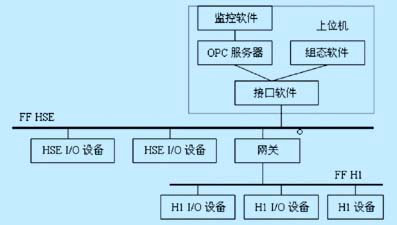
Take single-loop liquid level control as an example, the software operation of the upper computer:
(1) The HSEInit interface software selects the H1 network segment. The HSE interface program can interact with the HSE device in the Ethernet segment and the H1 segment device under the LD device to provide data access interfaces to upper layer software such as configuration.
(2) Run the configuration program FF-Configurator configuration software to refresh the network segment to obtain the system's field device list and function block list. After the network segment is refreshed, the application is completed and the function block configuration is completed. The connection line between the function blocks indicates that Bus communication signal connection, as shown in Figure 2;
(3) FFH1 and FFHSEOPC servers are refreshed once per second to realize real-time data sharing and alarming functions of the equipment;
(4) Design SiaView monitoring software, create a new project, select the PID in the object and drag it to the view. After editing with OPC, you can get a PID function block operation panel.
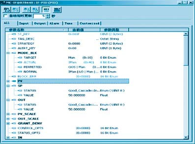
Select the IF-AI1 function block, IF-PID function block, and FI-AO1 function block from the device configuration window of the configuration software and drag it to the application view to configure a PID control loop. See Figure 2. The functional blocks are connected and the connection between the functional blocks is established so that the parameter blocks can be transferred between the functional blocks and the configuration information needs to be downloaded to the field device. Correct operation of the level control loop requires modifying the parameter values ​​of the function block. Double-click the IF-PID function block to open the parameter window of the block. Change the TARGET parameter in the MODE_BLK entry of the IF-PID to AUTO mode and read the function block parameters. In order to achieve a single loop of liquid level control automatically normal operation. If you want to implement the advanced control algorithm to the FF fieldbus system, just modify the TARGET parameter under the MODE_BLK item in the IF-PID to the MAN mode, as shown in Figure 3, and then implement the process variable through the OPC technology. Communication with control variables. 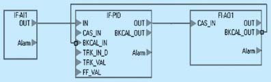
3, based on OPC PID control program to achieve advanced control algorithm based on FF fieldbus, first to achieve the basis of conventional PID control, including advanced control algorithm software to read and write hardware device information through the OPC interface (as OPC customers), Access to process data through the OPC server can overcome the differences between heterogeneous network architectures and network protocols.
3.1 The OPC server uses the Shenyang Institute of Automation of the Chinese Academy of Sciences to provide the OPC server MicroCyber.FFServer.1. The address space of the server is composed of all data items that the server can read and write. The full name of the data item can be used to perform related operations. Figure 4 shows the address space of the OPC server. Using OPC technology to achieve communication with the OPC server client program written in VB6.0, the real-time value of the liquid level in the server IF-PID-PV.VALUE, and custom variables such as the level settings IF-PID-SP. VALUE, then the algorithm control, get the control quantity, write the control quantity into the item FI-PID-OUT.VALUE of OPC server, thus control the controlled system. 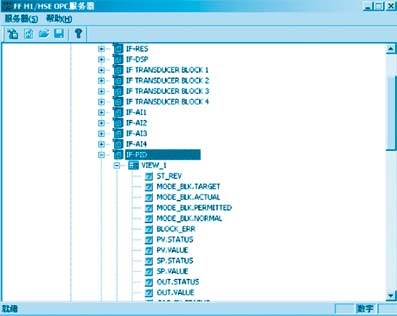
3.2 OPC Automation Interface Standards (1) Automation Interface The OPC Foundation provides two types of interfaces for data access specifications to facilitate user development in various environments: automation interfaces and custom interfaces. Based on the development of custom interfaces, deeper COM/DCOM knowledge is needed, which is relatively obscure, and the use of automation interfaces has the following advantages: The client program can easily apply the interface without understanding the detailed internal mechanism of the interface; Use event triggering; you can generate a generic dynamic link library (DLL) or control for use by all client applications.
(2) Communication mechanism of the automation interface The OPC client program accesses the OPC server through the encapsulated OPC automation interface dynamic link library, as shown in Figure 5. The dynamic link library translates the custom interface of the OPC server into the automation interface that the OPC client wishes to call for the client program. The OPC client and dynamic link library are in-process communication, and the dynamic link library and OPC server communication is based on COM/DCOM. It can be either in-process or local connection, or remote connection. The encapsulated dynamic link library solves the interpretation of the custom interface and the communication between the two, thereby greatly simplifying the development of the OPC client program. 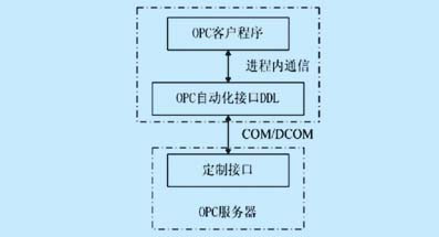
(3) The key to the development of the automation object model OPC client program is to find out the package structure of the dynamic link library, that is, the automation interface standard. This standard can be represented by the automation object model shown in FIG. It is mainly composed of six types of objects:
OPCServer: An instance of the OPC server. Only after creating the OPCServer object can the information of the OPC server be obtained. It includes the search of OPCGroups and the creation of the OPCBrowser object.
OPCGroups: Automatically collect all OPCGroup objects created by the client in the OPCServer range;
OPCGroup: An instance of the OPCGroup object. It contains all the status information and provides the necessary services for the OPC-Items involved in the OPC Group;
OPCItems: Automatically collect all OPCItem objects in the corresponding OPCGroup created by the client within the OPCServer range; 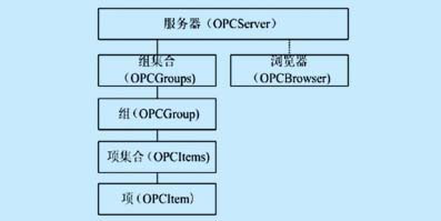

The single-loop control process is self-regulating and non-oscillating, and has a dual-capacity process that influences each other. Its mathematical model can be described by the following transfer function:
G(s)= ![]()
In the formula, Kp, Tp, τ are the gain, time constant and time lag of the process. Each parameter in the formula can be calculated graphically based on the step response curve. The method for determining the parameters of the transfer function is given below: Let the control quantity in Fig. 7 be q, and the measured value be y(∞). The new steady state value is the set value. The gain K can be directly calculated from the steady state value of the input and output. , and Tp, τ can be used as a map to determine. In order to call the measured value y collected on the OPC server at any time and draw the corresponding step response curve, the selected data is stored in the specified database (using the SQL2000 database). At the same time, in order to simulate the algorithm, the data can be taken from the historical database, or as the data is collected, the data can be continuously refreshed to optimize the algorithm, as shown in FIG. 8 . 
4. Summarize the design process of the process control experiment system through the FF fieldbus and discuss the OPC technology. The purpose is to develop the OPC automation interface client application through VB, and realize the application programming of the PID control algorithm to the OPC client application. The use and maintenance and upgrade of the system, while studying the SQLServer2000 database system for historical data access and algorithm simulation. How to implement a more sophisticated advanced control algorithm, you can use OLE automation technology to achieve mixed programming of VB and Matlab, that is to use VOB to write OPC client program to achieve data communication, and use Matlab to write advanced control algorithms, and thus on-site data Analysis is the focus of the next step.