Design and application of operating room power distribution and insulation monitoring system
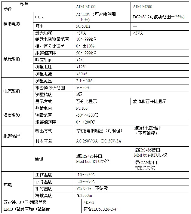
Xu Shuang Ankerui Electric Co., Ltd. Shanghai Jiading 201801 Abstract The design and application of operating room power distribution and insulation monitoring system are discussed with reference to the regulations and requirements of the IEC standard for the system-level insulation monitoring system of the power supply in the operating room. The measurement principle of the insulation monitoring instrument is discussed. And the scope of application; analysis of IT system grid ground faults and their limitations. Key words operating room distribution insulation monitoring IT system grid fault At present, a large number of electrical medical devices are collected in the operating room of the hospital, among which the medical electrical equipment that contacts human internal organs (hearts), brains and other organs needs to be monitored for insulation and special protection. In our country's standards and specifications, the provisions for the design of medical electrical equipment safety protection and insulation monitoring are not detailed or comprehensive, and have not yet been able to communicate with IEC 364-7-710 (Electrical Installation in Buildings Part 7: Special area installation requirements) Standard connection. The author discusses the design and equipment selection of the power distribution and insulation monitoring system in the operating room. 1 IEC standards for operating room power and insulation monitoring IEC 364-7-710 (1997) ("Electrical Installation in Buildings") Part VII: Requirements for Special Installations in Special Areas Section 710: Medical Places for Grouping and Uninterrupted Power Supply According to Risk of Electric Shock Requires classification, and belongs to the 0.5-category site of the second application group, with only the surgical preparation room, operating room, and special nursery room; for the above-mentioned site, IEC 364-7-710•413•1•5: Except IEC 364-7 Equipment other than those specified in -710•413•1•3, medical electrical equipment, lighting, and similar lighting equipment for life or surgical operations, equipment with a rated voltage exceeding AC250V or DC60V, must use IT equipment with insulation resistance monitoring equipment Power system, the instrument should also satisfy: 1 ​​internal AC insulation resistance must be greater than 100KΩ. 2 The test voltage is not more than DC25V. 3 The test current must not exceed 1 mA even under fault conditions. 4 At the latest when the insulation resistance has dropped to 50KΩ, there should be a display, and a test instrument should be provided to test the device. 5 If the ground wire or circuit connection is loose, there should be a display. 2 Provisions and Problems of "Civil Building Electrical Design Code" (JGJ/T16-2008) In the "Civil Building Electrical Design Code" (JGJ/T16-2008) (hereinafter referred to as "the People's Regulations"), only in Article 14.7.6.3 that "after the sudden interruption of power supply, there is a risk of causing serious medical care, should be used The power system is not grounded (IT system power supply mode). Article 14.2.8: "The IT system must be equipped with an insulation monitor and ground fault alarm or display device." In some actual designs, the medical isolation transformer is used only for the important medical sites, the IT system power is drawn, and an insulation monitoring device is set in the room distribution box. The system diagram is shown in Figure 1. Figure 1 IT system insulation monitoring The above design is too simple and general, and some measurement methods of the insulation monitoring instrument are backward, which can not accurately and reliably display and alarm, leaving a great hidden danger for the distribution of the operation room and other important medical sites. 3 Design of operating room distribution and insulation monitoring system According to “Part I: General requirements for safety†in the “Medical Electrical Equipment†(GB9706.1-93), in combination with IEC 364-7-710 and “Public Regulationsâ€, the author summarizes the experience of designing electrical distribution and insulation monitoring in the operating room. The operating room distribution and insulation monitoring are discussed as follows. 3.1 Design Examples a. The monitor uses the products of Ancorui Electric Co., Ltd. b. Since the operating room is equipped with a large number of single-phase medical electrical equipment, the IT system power supply requires the N-line. According to the requirements of Article 8.6.6.6 of the "Public Regulations", an over-current protector shall be installed on the N line. Therefore, a two-pole (single-phase) low-voltage circuit breaker is used to cut off the phase line or the N line when a second phase-to-ground (short-circuit) fault occurs in the IT system power supply. c. Use the AITR6300 isolation transformer to meet single-phase load requirements. d. AIM-M series insulation monitor is used. It has the following functions: 1 It monitors the insulation resistance and the range is 10~999KΩ. 2 Monitor the load current in the range of 2.1 to 50A. 3 Monitor the isolation transformer temperature. 4 online monitoring instrument and power grid, N line, PE line connection. 5 online monitoring instrument and current transformer connection. 6 online monitoring instrument and temperature sensor connection. 7 two relay alarm output, LED alarm indication. When the AIM-M series insulation monitor is connected to the current transformer AKH-0.66P26, it can be used to monitor the load condition of the isolation transformer; the temperature sensor PT100 inside the isolation transformer (terminal ST in Figure 2 and Figure 3) can be monitored. Transformer temperature conditions. e. Select AID series external alarm and display instrument, installed on the operation room information control panel, display all the information of AIM-M series insulation monitor, and have the function of remotely setting alarm parameters of AIM-M series insulation monitor. f. The communication between each instrument in Fig. 2 is realized through the RS485 interface. The communication between each instrument in Fig. 3 is realized through the CAN interface. g. Use the instrument-specific power supply ACLP10-24 to ensure the reliability and stability of the power supply used by the instrument. ACLP10-24 can convert AC220V to DC24V. 3.2 Typical design diagrams of operating room power distribution and insulation monitoring systems In accordance with the principle of selection and design of the above-mentioned instruments, the power distribution and insulation monitoring system diagram (without fault location) of the single-phase IT system in the operating room is shown in Fig. 2, and the functions and quotations of the instruments are shown in Table 1. Figure 2 Single-phase IT system power monitoring system wiring (without fault location function) Table 1 Function and Quotation Table of Instrument without Fault Locating Function name model Features Price (yuan) Insulation monitor AIM-M100 It has the functions of real-time monitoring of insulation resistance, isolation transformer load current, transformer winding temperature and fault alarm for the monitored IT system. 15600 DC power supply ACLP10-24 Instrument dedicated DC voltage regulator module, rail mounting 300 Alarm and display AID100 With insulation resistance, variable pressure load rate real-time display function; can be remotely set the alarm value of the insulation monitor. 900 AID120 Current Transformer AKH-0.66P26 Protection type current transformer used with AIM-M100 insulation monitor. The maximum measurable current is 50A and the ratio is 2000:1. 150 The operating room single-phase IT system power distribution and insulation monitoring system diagram (with fault location function) is shown in Figure 3, and the instrument function and quotation are shown in Table 2. Figure 3 Single-phase IT system power monitoring system wiring (with fault location function) Table 2 Function and Quotation Table of Instrument with Fault Locating Function 3.3 Instrument selection and installation: A. Technical data and parameters of the instrument: AIM-M series insulation monitor, AITR series isolation transformer, AID series alarm and display instrument, ASG100 test signal generator, AKH-0.66P26 current transformer, AIL100 insulation fault locator, ACLP10 The technical parameters of the -24 power supply module are shown in Table 3 to Table 9, respectively. Table 3 Technical parameters of AIM-M series insulation monitor Table 4 Technical parameters of AITR series isolation transformer Table 5 AID series alarm and display technical parameters Table 6 Technical parameters of the ASG100 test signal generator Table 7 Technical parameters of AIL100 insulation fault locator Table 8 Technical parameters of AKH-0.66P26 current transformer Table 9 Technical specifications of the ACLP10-24 power module B. Installation: The isolation transformer can be installed in the power distribution room near the operating room in the hospital. The AID series alarm and display devices are installed in the operating room or monitoring room where they can be easily observed and operated, and are mounted on the wall. 4 Types of insulation monitor and monitoring principle The insulation monitor continuously monitors the insulation of the IT system grid. When the insulation value drops to the pre-designed response value, an audible and visual alarm is issued to enable the insulation fault to be timely monitored and maintained, ensuring the reliability of the IT system's power supply. . 4.1 Superimposed DC Measurement Voltage Method A direct current measuring voltage is superimposed between the power grid and the protective conductor. The positive pole is connected to the power grid via a high-impedance coupling resistor, and the negative pole is connected to the earth via an electronic circuit. When the IT system grid has an insulation fault, the measuring circuit is closed at the insulation fault. At this time, the DC measurement current I m ​​flows through the measurement resistor R m through the insulation fault, and I m is evaluated by the electronic circuit. Figure 4 principle of superposition DC measurement voltage method This measurement method can only be used in pure AC single-phase or three-phase power grids. If there are DC components, large capacitors in the power grid, or changes in voltage and frequency, the accuracy of the method will be affected. 4.2 Asymmetric voltage measurement The measurement method uses a bridge circuit to connect with the two poles of the monitored grid, as shown in Figure 5. No voltage signal is superimposed on the grid, but the grid voltage is used as the drive voltage. When a phase occurs to earth fault, it will cause voltage drift. Rf+ or Rf- drive measuring current I m. The current is recorded by the electronic circuit. When the value reaches the response value, the alarm relay will act. A balanced short-circuit to earth fault occurs and the instrument cannot identify the fault. The method cannot directly show the kΩ-level insulation fault to ground. This measurement method is suitable for use in a DC grid. Figure 5 Principle of asymmetric voltage measurement 5 IT system grid ground fault analysis When the first ground fault occurs in the IT system power grid, according to Article 8.6.4.15 of the “Civil Regulationsâ€, the power supply can be automatically cut off, and an insulation monitor can be used for sound and light alarms. The fault should be eliminated within the shortest time. For example, if the second ground fault occurs in the IT system power grid, as shown in Figure 6, after ground fault occurs on device I, ground fault occurs on device II. The fault point is subject to line voltage, causing a short-circuit fault. Operating rooms, surgical preparation rooms, and special care rooms are geographically distant from each other in the hospital. The external conductive parts of the medical electrical equipment are each grounded. If there are several medical electrical equipments located close to each other or in a unified room, they should be used. Common grounding. Figure 6 IT system insulation monitoring references [1] Yang Chengde. Design and discussion of operating room power distribution and insulation monitoring system [2] Wang Houyu. Electric safety requirements in hospitals. Building Electrical, 1993(4):~7 [3] Yang Chengde. Grounding and zero protection of low-voltage distribution system. Journal of Electrical Engineering, 2000(7):23~26 [4] Yang Decheng. Power supply and safety protection design of medical electrical equipment. Supply and use, 2000(5): 41~43 About the Author Xu Shuang, female, undergraduate, Ankerui Electric Co., Ltd., the main research direction for medical power distribution design, mobile phone QQ Aluminium Circle,Aluminium Circle Sheet,Aluminum Circle Sheets,3003 Aluminum Discs Zhengzhou Yearshine Industry Co., Ltd , https://www.zzyscorp.com