Vacuum coating system with orientation and self-control
2 Improvement of Vacuum Coating System Instructor: He Tianmin (1964-), male, Baishan, Jilin Province, Professor and Ph.D. of School of Physics, Jilin University, mainly engaged in the research of rare earth solid oxide functional materials and modern physics. Although the coating system has the advantages of simple equipment and easy preparation process, it also has serious waste of film material during coating, weak bonding force between the plating layer and the substrate surface, slow deposition rate, serious impact on the macroscopic particles, 121 film thickness is not Uniform, difficult to control film thickness and other shortcomings. Therefore, this paper has improved the existing vacuum coating system, so that it has the function of directional coating and automatic control of the coating process. The orientation device consists of an evaporator, a cone-shaped funnel and a funnel bracket. The conical funnel is detachable to facilitate the filling of coating materials. Since the evaporator provides a semi-closed ring, the membrane molecules diffused to the surface of the substrate in a tapered funnel direction, avoiding the waste caused by scattering of vapor molecules and keeping the vacuum chamber clean without the need for every plating. The bell jar is cleaned, and when the molten membrane material is vaporized, a small amount of incompletely melted film material and simultaneous evaporation of tungsten and other impurity molecules and large particles of the film material melt are prevented from splashing on the substrate, thereby preventing rough surface of the film. When the degree is large, the adhesion of the film is reduced, the density of the film is not uniform, and defects such as a decomposition surface occur between the macroscopic particles and the continuous film in the film layer. At the same time, due to the semi-enclosed environment in the evaporator, the temperature of the evaporated gas molecules in each part is also approximately the same, so that the film layer and the substrate are combined more uniformly, denser and stronger in binding force. The film thickness control device consists of a film thickness detection device and a baffle automatic control device. The film thickness detecting device is composed of a quartz oscillator-type microbalance equipped with a high-sensitivity pressure sensor and a control circuit ( ). Baffle automatic control device () consists of electromagnets, permanent magnets and baffle parts. The baffle portion includes a baffle base, a movable baffle with a rotating handle, a rotating handle with a chute, a spring A, a spring B, and the like. The elastic coefficient kB of the spring B is greater than the elastic coefficient kA of the spring A. The coil of the electromagnet is connected to the high-sensitivity pressure sensor in the quartz oscillator type microbalance via a control circuit, and the control circuit is mainly composed of a coil, a microbalance, and a high-sensitivity pressure sensor. , relay switch (equivalent to double-pole double-throw switch), keys, conductive contacts and power supplies. When each part begins to be coated in detail, the rotating baffle of the movable baffle is placed on the seat a, that is, the open state. At this moment, the electromagnet coil at the end of the turning shank turns on the current through the control circuit so that the generated magnetic field is in the same direction as the magnetic field generated by the permanent magnet outside the bell jar, ie they will attract each other, and the spring A is in a slightly stretched state; the spring Although B is in a highly compressed state, because its connection point on the rotating handle is close to the axis of rotation of the living cloud force baffle, its rotational moment to the movable baffle is close to 0, and it is completely rotated by the deck a. The rotation torque of the handle is offset, so the movable baffle buckles at the seat a and does not move, and the baffle is in a stable open state. When it arrives. In this way, the degree of ionization of the vapor of the metal film material is greatly increased, and to a certain extent, the directionality of vaporized molecules of the vapor film is higher, and the deposition process is accelerated. By controlling and adjusting the voltage between the positive and negative poles, the rate at which the film is deposited on the substrate can be controlled and adjusted. Substrate transmission is mainly composed of a small motor, a sliding ring, a fixed ring, a transmission belt and a ball. The top view is as shown, and the longitudinal section of the center portion is as shown. The slide ring is in the form of a steel ring and can be driven by the drive belt to rotate around the fixed ring; one end of the drive belt is driven by a small motor and rotates at a constant speed, so that the film of each part of the substrate during coating is more uniform. The substrate temperature control device is mainly composed of an auxiliary resistance heater. By adjusting the current in the resistor, the temperature of the surface of the substrate can be controlled, so that the temperature can be adjusted to an appropriate temperature so that the film layer adheres more closely to the substrate. If there is a strict requirement on the substrate temperature, the laser temperature measurement can be used at the same time. 14. The evaporation source and substrate spacing control device consists of three pairs of flat height-adjusting nuts and threads engraved on the post, as shown. Tighten the three pairs of height-adjusting nuts to fix the base plate bracket. By turning the three pairs of height-adjusting nuts up and down simultaneously, the height of the base plate bracket can be controlled to control the distance between the evaporation source and the base plate. The height-adjusting nut is made to be relatively flat and flat in order to keep the entire baffle base in a horizontal position as much as possible. In addition, if there are strict requirements on the impact of oil pollution, a dry vacuum pump 151 or a molecular pump 16 may be used instead to achieve a cleaner purpose. In practical applications, the six devices designed are not only limited to their individual functions, but are beneficial to each other. For example, the electric fields generated by the positive and negative electrodes in the deposition rate control device also evaporate the film vapors. The directionality is better, the orientation device also makes the film layer more uniform and dense; through the substrate drive device, substrate temperature control device, orientation device, evaporation source and substrate spacing control device and deposition rate control device and other collaborative work Therefore, the uniformity of the film layer is ensured, and the film layer and the substrate are also more closely attached. 3 Conclusion With the vacuum coating system with orientation and self-control functions, the deposition of coating material is more concentrated, which not only saves the film material, but also makes the vacuum chamber environment cleaner; the deposition rate is accelerated, and the film thickness is more uniform and dense. The bonding force with the surface of the substrate is greatly enhanced, and real-time control of the film thickness can be achieved. The density of the deposited film is more uniform and the purity is greatly improved, thereby achieving control and significantly improving the quality of the coating.
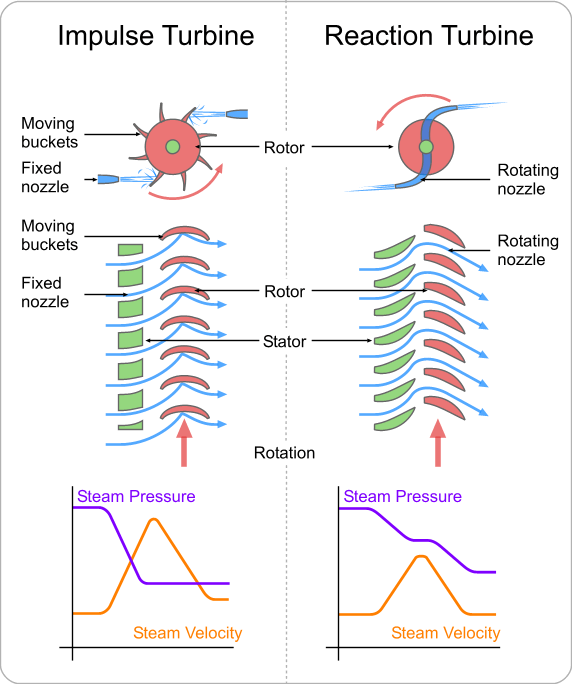
An impulse turbine is a type of Steam Turbine where the rotor derives its rotational force from the impact force, or the direct push of steam on the blades.
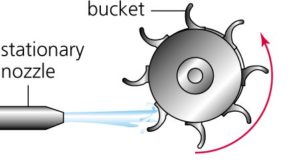
The impulse turbine consists of a rotor mounted on a shaft that is free to rotate. Attached to the rotor are a set of curved blades. Nozzles then direct the high pressure and high temperature steam towards the blades of the turbines. The blades catch the impact force of the rapidly moving steam and rotate from this force.
The steam at high pressure enters through a stationary nozzle of a steam turbine, as a result the pressure of the steam is decrease and an increase in steam velocity. As a result of increased steam velocity steam pass through the nozzle in the form of a high-speed jet. This high-velocity steam hit the properly shaped turbine blade, as a result, the steam flow direction is changed. The effect of this change in direction of the steam flow will produce an impulse force. This force cause the blade move, thereby the rotor will start to rotate.
The force applied to the blade is developed by causing the steam to change the direction of flow (Newton`s 2nd Law – change of momentum). The change of momentum produces the impulse force.
In the impulse turbine pressure drops and the velocity increases as the steam passes through the nozzles. When the steam passes through the moving blades the velocity drops but the pressure remains the same.
The fact that the pressure does not drop across the moving blades is the distinguishing feature of the impulse turbine. The pressure at the inlet of the moving blades is same as the pressure at the outlet of moving blades.
Impulse Steam Turbine Shandong Qingneng Power Co., Ltd. , https://www.steamturbine.be
The Impulse Principle
Impulse Turbine Working:
